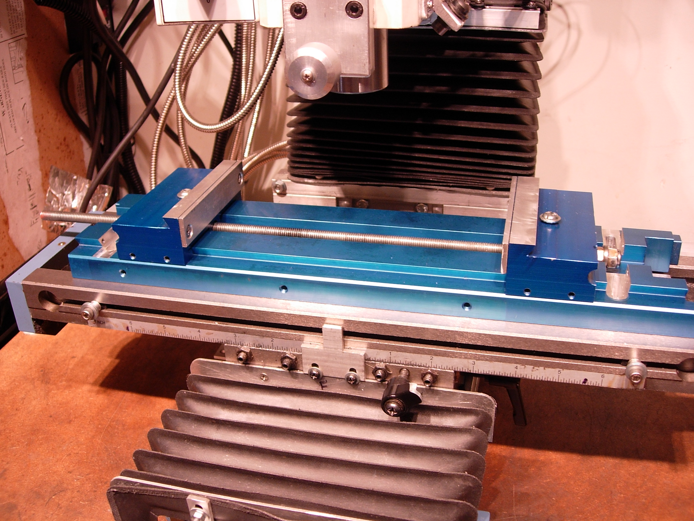
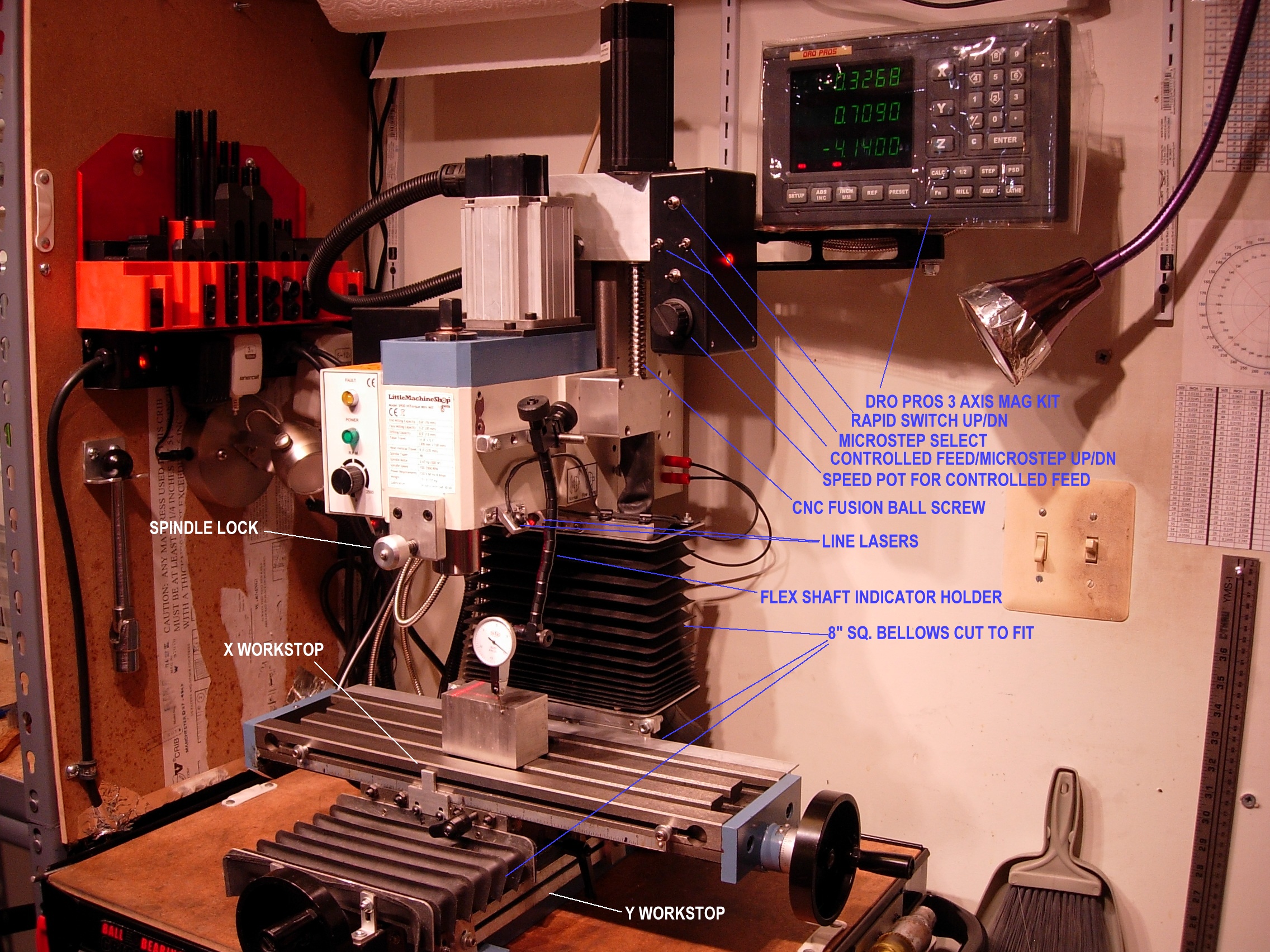
Back to Swarf Page


LMS 3900 Mods


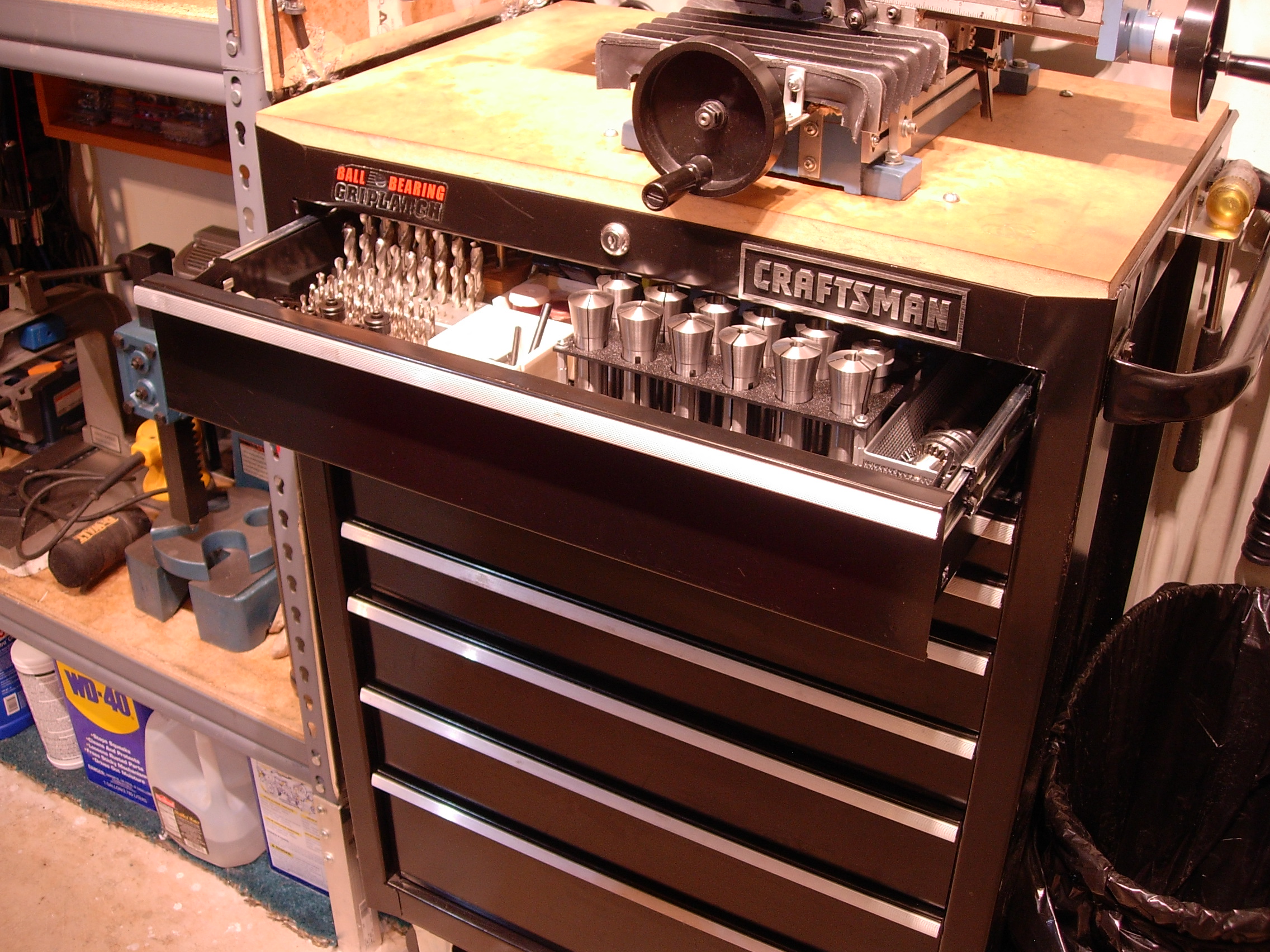
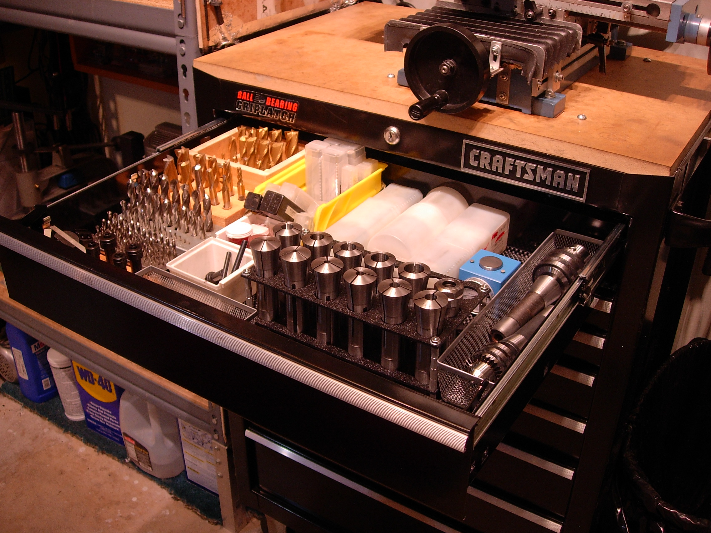
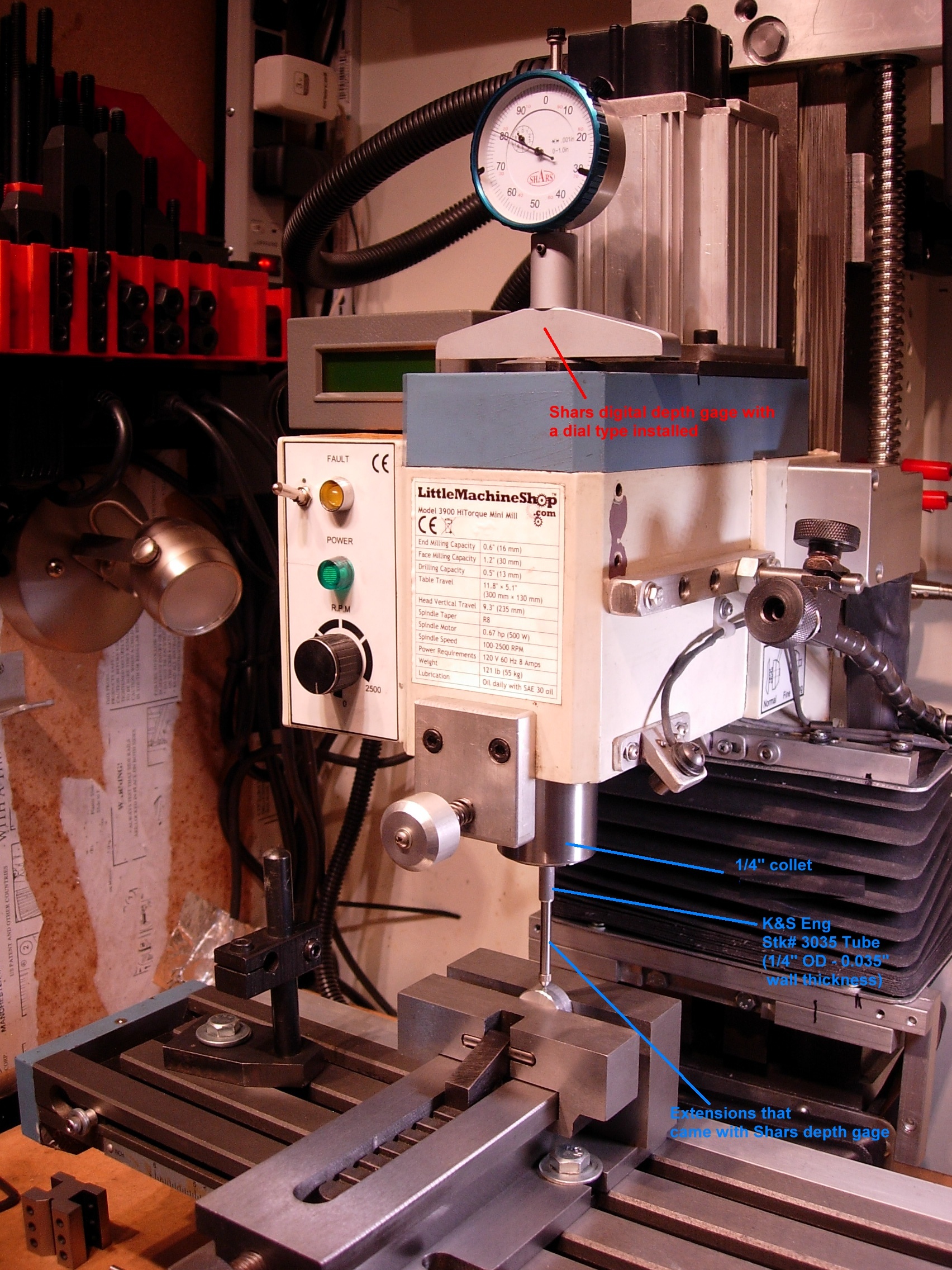
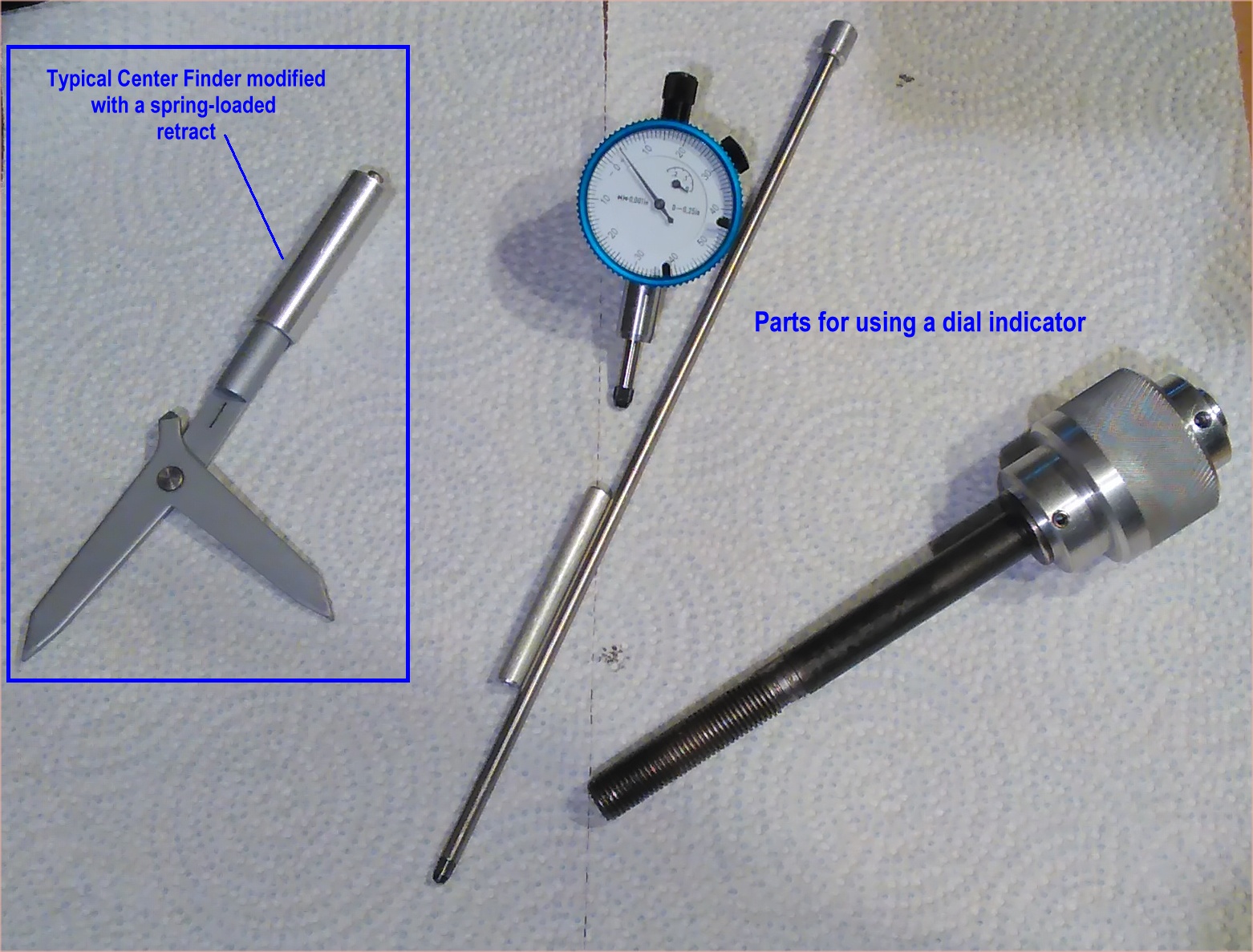
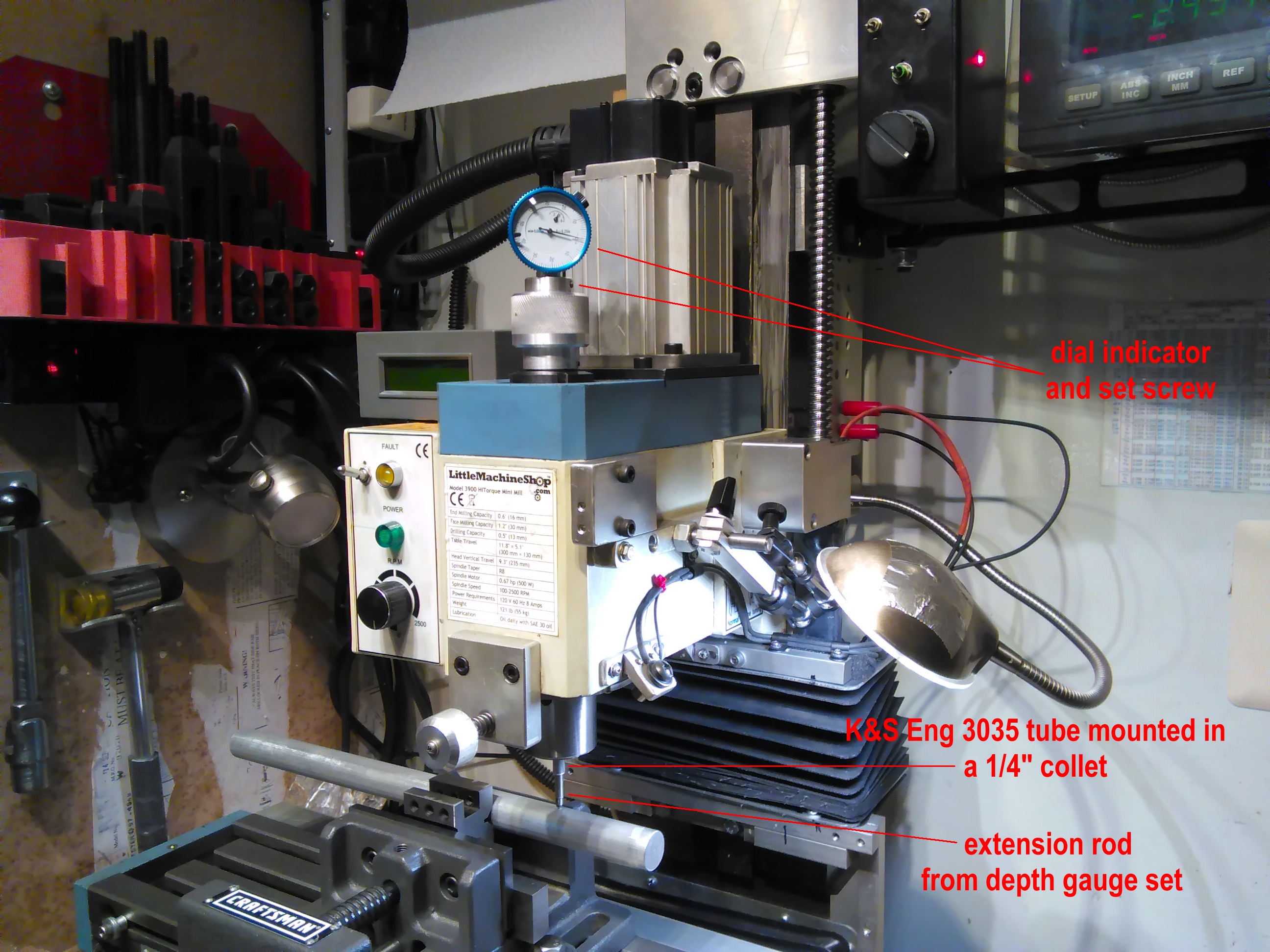
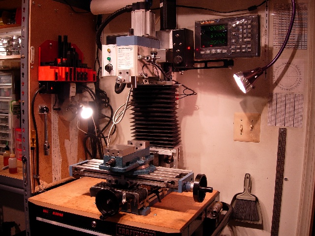
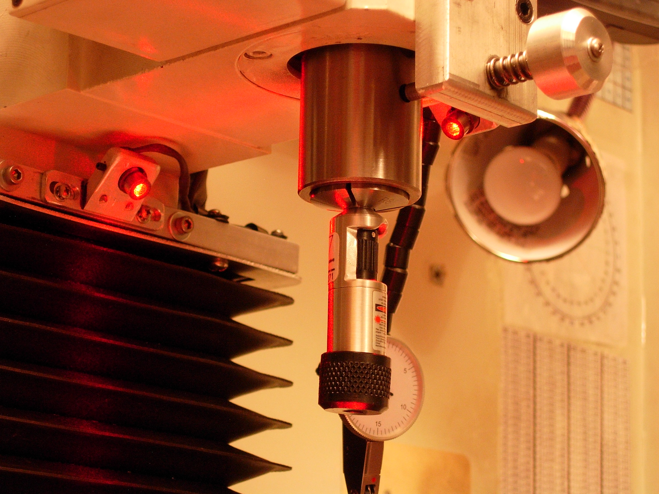
Click above for newer
Extended Solid Column Pics

Mill Microscope with display - click for larger image
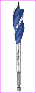
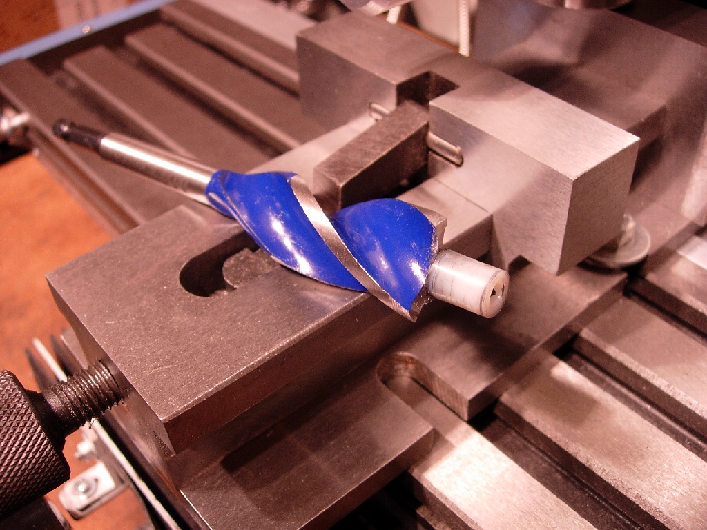
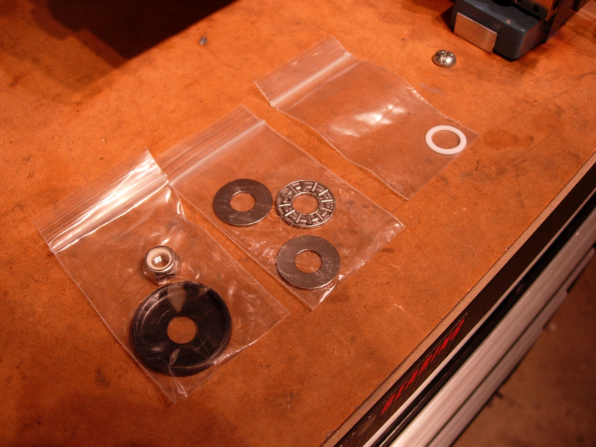
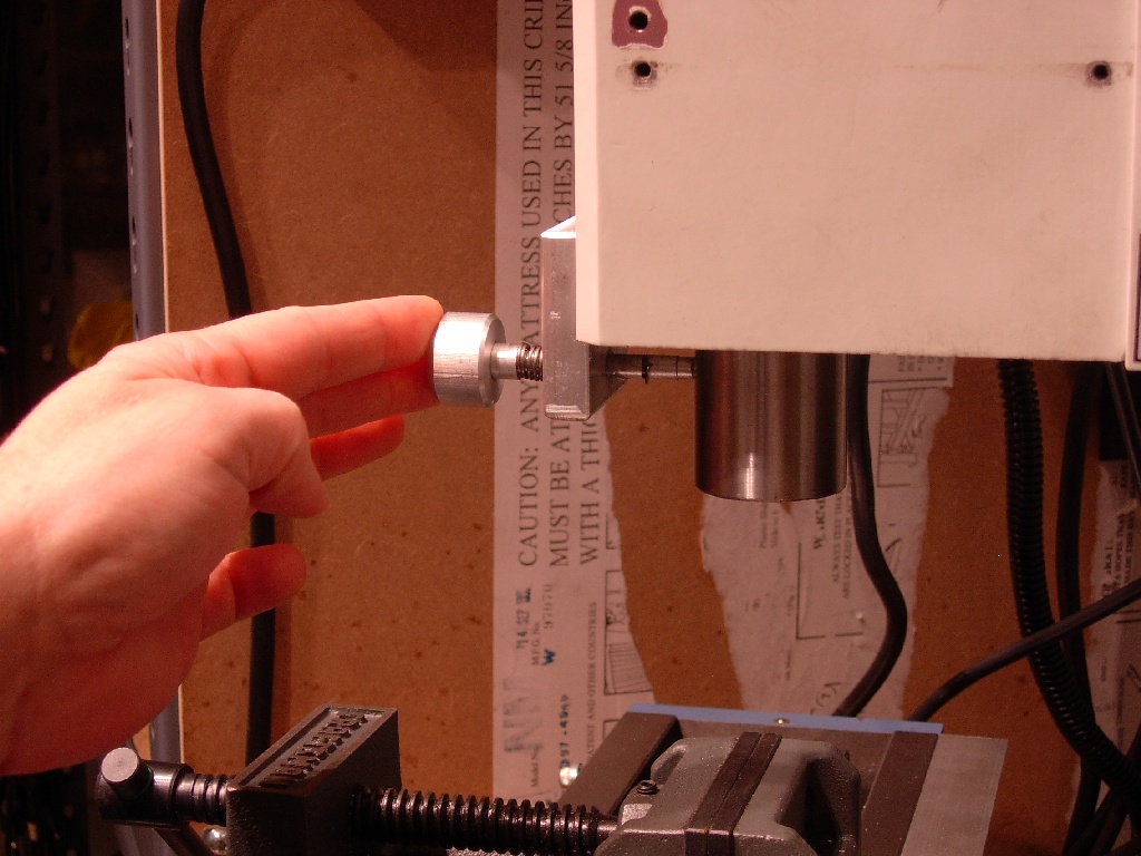
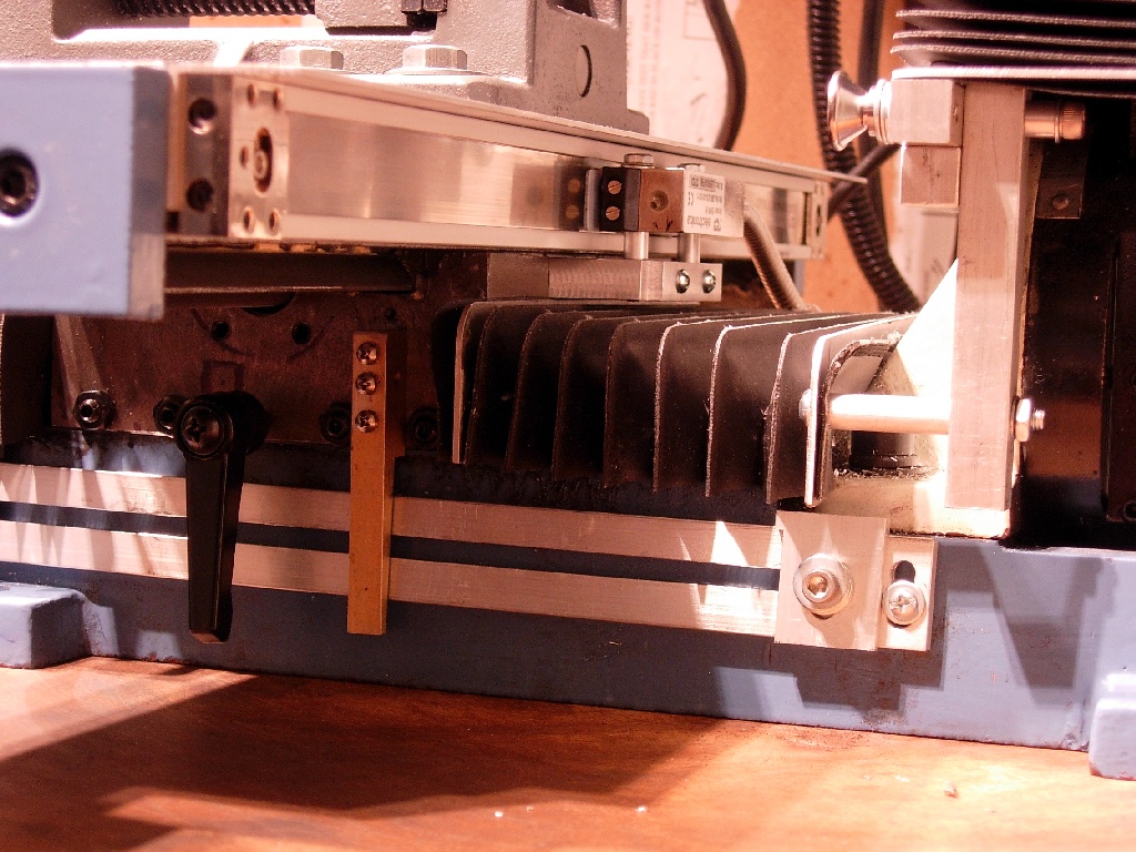
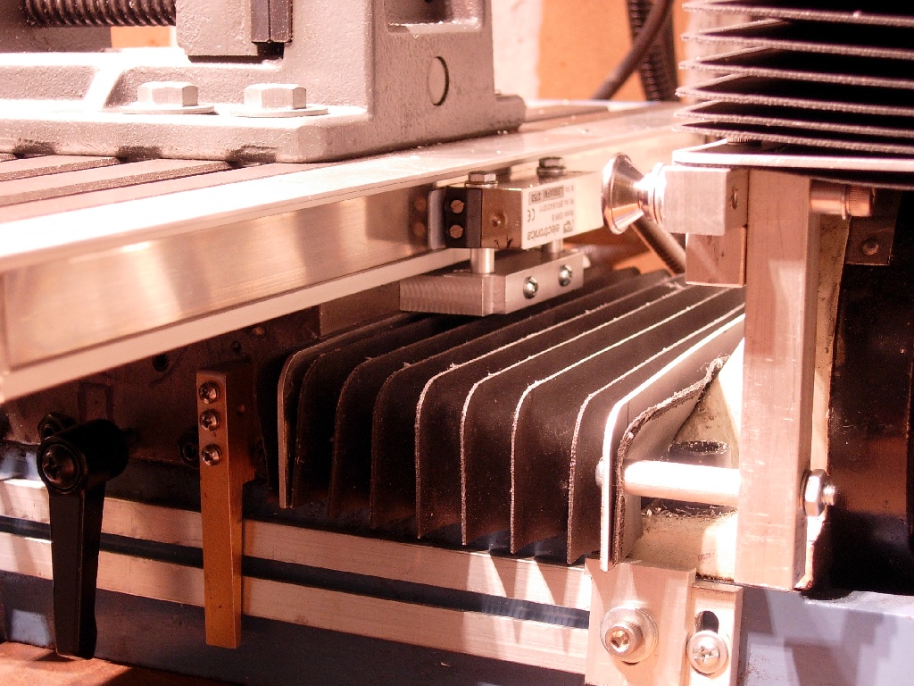
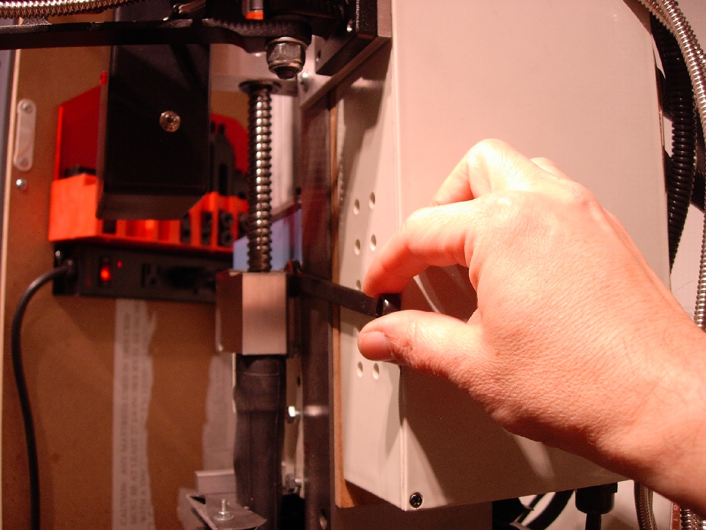

(click image to enlarge)


I used the stock Sieg Z axis thing for about two minutes - couldn't stand it. Head drop sucked.
Bought a CNC Fusion Z kit to make a system similar to the one on the X4... see further down on the page for more info

Links to vids -  it can microstep a little over 1/10 a mil... 0.00012" .  The speed pot can vary from continuous to single steps/Microsteps.

http://www.ajawamnet.com/ajawam3/swarf/DSCN2381.wmv
http://www.ajawamnet.com/ajawam3/swarf/DSCN2316.wmv
http://www.ajawamnet.com/ajawam3/swarf/DSCN2317.wmv

Bellows mounting made with just a saw and a drill press (real GETO).
These are square (I cut to fit), rubber-coated polyester McMaster bellows ,  w/flanges cut to fit
http://www.mcmaster.com/#9742K35
http://www.mcmaster.com/#9742K45
Lost no travel from the rated 11.9 X and 5.1 Y

Initially I tried using the Igaging readouts - they reset arbitrarily. Ripped them off after a week.
Bought a real DRO from DROPRO's
Nice... f'ing nice...

Note the work stops for the X and Y axis
Added a set of line lasers to the head stock
Added a flexible indicator holder mounted to the head stock


More pics:


Note how I used metric hex heads to set the spacing for the DRO mag head reader since there's no clearance
Didn't use any of the tons of hardware DROPRO's supplies - too big for this size machine


Added a set of line lasers and a flexible shaft indicator holder (click either image to enlarge):
 
Line lasers were added to allow me to quickly set X and Y without having to pull mills/bits to reset a workpiece. The Y laser is aligned with the table for quickly setting up vises/fixtures. I used the SDA spindle laser
to set up the line lasers to be accurate at any head stock height (not easy...)... gets it to within a few mil... The flexible shaft indicator holder is also great; always there and ready (no fudging with a zillion pivots)


I wanted a manual mill, something to rough stuff in and do basic milling. As a drill press, the X2 (even the LMS with the larger travel) has little clearance to the table with an R8 chuck arbor and 1/2" chuck; ie. don't get rid of your drill press...
The Z sucks... drops pretty bad. You can use the gib lock but it changes your depth/tram slightly. The trick of going past the cut depth then raising it:

http://www.mini-lathe.com/Mini_mill/Features/features.htm#Backlash
http://www.machinistblog.com/the-mini-mill-head-drop-problem/

is OK for something like squaring a block, but it's tough if you're doing pockets...

I figured that the best thing to do was add a leadscrew - the CNC Fusion thing looked best. But the common complaint was the housing for the ball nut on the spindle covers up the hex gib screws:
http://www.machinistblog.com/cnc-fusion-z-axis-modification/

So I came up with this:
1- move the dang electrical box so it's flush on the gib side of the column- this ain't easy since it has two ground screws in the column - I'm using a piece of MDF with tnuts, slotting it so that a wire can be brought out to the slot in the moved enclosure, then screwing the box on to tnuts... it'll help absorb some shock too... How I routed the chassis ground:
http://www.ajawamnet.com/ajawam5/DSCN2292.JPG

2 - Go to the auto parts store and get some hex screws 6mm x 20 - 1mm pitch

3 - lathe the end down to match the gib slot - use a soft jaw and mod it like this by reversing the jaws, machining a slot to clear the bolt head, then flip the jaws back:
http://www.ajawamnet.com/ajawam5/DSCN2259.JPG

4 - replace the socket heads with the hex screws - use a bit of 242 locktite (just a bit) after cleaning out the crap in the hole

http://www.ajawamnet.com/ajawam5/x2gibscrew1.jpg
http://www.ajawamnet.com/ajawam5/x2gibscrew2.jpg

Viola - adjustable gib on the Z


I'm currently using a arduino and a 23MD 425 oz/in stepper from Anaheim (built in drive with microstepping - has an integrated Allegro 3979) to use it for now:
http://www.ajawamnet.com/ajawam5/DSCN2297.JPG

This is similar to what Sieg did on the SX4
http://www.mini-lathe.com/Mini_mill/Reviews/SX4/sx4-rvw.htm

eventually I'm doing this:
http://www.ajawamnet.com/ajawam5/zhandgear.jpg - I really want a manual mill.

I have to say tho that the Atmel based arduino thing I did allows it (in microstepping) to move down very small increments - the CNC Fusion ball screw is 0.2 TPI so at 1600 steps per rev it's 0.000125 . I can see why the guy that did the SX4 review mentioned it as "... One of the coolest - and most useful - features of the SX4..."

The top toggle is a center off DPDT momentary that tells the arduino to override the current pot and microstep settings for rapid moves
the two mini toggles set the arduino's microstepping outputs
the lower toggle is another DPDT momentary for the pot controlled movement/microstepping
the pot is connected to one of the Atmel's analog to digital converters to set the pulse rate

Works really well - very solid entry into cuts.

One thing about the CNC Fusion Z axis kit - for mounting the stepper/bearing block, CNC Fusion supplies two cap screws - you are supposed to drill and tap or drill thru/use nuts where  the two counterbore holes are in order to add support for the top column Z block. There's little clearance - the spindle motor mount is close to the column; hence the use of counterbore cap screws.

The problem - the bottom of a cap screw in a counterbore offers little contact at the bottom of the bore, so during deep cuts and accidental stalls, the entire Z mount will rotate. This causes the ball screw to misalign with the spindle mounted ball housing/ball nut. I noticed this when I first did the install, thought maybe I screwed up. Then during a nasty time milling some cast iron for my Deckel SO clone, I saw it happen again. I tested it during a controlled stall; sure enough, you could watch the Z motor mount tilt.

So I needed to quickly do a mod to it and of course, on weekday evening. I decided to add some 3/8" hex bolts on either side of the cap screws, problem was the clearance. I needed to make the 3/8-16 hex flush with the face of the Z mount so I needed a shallow counter bore that would allow a 9/16" socket to clear.


I went to Lowes, bought a 7/8" Irwin Speedbor three flute boring tool. They're made with a small helix starting point on the end and have small points at the end of the flutes. Made for wood, it actually cut the AL pretty easily.

After lining up the Z mount and tightening the stock cap screws I began by drilling the 3/8-16 clearance hole (I decide to thru hole it with nylok nuts/washers inside the column - if I over torque/snap the bolt no big deal)  I ground the pointy tips of the Speedbor off the flutes, and found a nylon spacer that was about 3/8 OD and just threaded onto the small starting point to act as the counterbore guide.  Since the Z mount is only 0.400" thick the counterbore has to be shallow... therfore the hex head bolts needed to be faced down on the lathe. I happened to have some small OD washers that fit the 7/8" counter bore perfectly.

Works well; during a controlled stall, the stepper now stalls and the Z mount does not move and the spindle head still clears the Z mount.


Gib nut wrench
Cool tool to set gibs - did this years ago for my MaxNC (I haven't used a stick welder in 30 years - that's apparent):
It's a 12 point Craftsman deep well socket welded to a crap box end wrench. I had to grind it down to fit next to the Y stop I made


In the next section I talk about the custom MAXNC I had Mitch make for me - larger table and axis.
I've had many a MaxNC, starting with a 10, going to a 15 with an 18" table and eventually paying Mitch at MaxNC to make me a custom super Maxnc.


So I had a bunch of parts left over, decided to make a vise out of them. I lock the gibs on one side, and adjust the other side's gibs for minimal lifting. Works well on light-med duty milling.
I made it so it will either fit the MaxNC or the LMS 3900.  There's some vids of it in use in the MaxNC section below.

Mill Cart
When I was looking for a roll-around cabinet for the mill, I came across a Craftsman 59619 at the local Sears. One of the features I wanted was to be able to have a top drawer
that was deep enough for storing mill cutters and R8 collets.


Just fits


I bolted thru the standoff (I used a bunch of 6-32 x 0.5" x 0.25"hex I had lying around) to the drawer bottom - otherwise the holder rocks around when the drawer is closed.
Just some scrap 0.125" thick ABS plastic I had from a thermoform job.

Here's some files if anyone wants to build one:
http://www.ajawamnet.com/ajawam3/swarf/holder.pdf
R12 DXF:
http://www.ajawamnet.com/ajawam3/swarf/holder.DXF

I used my CNC with an Onsrud 0.0625" single flute cutter (made for cutting plastic) to make it - typically for large hole cut-outs I tab the toolpath to keep the cutout from fouling the job:
Video link
http://www.ajawamnet.com/ajawam3/swarf/DSCN2883.wmv

CNC toolpath report - click on the image on that page and you'll see the tabs:
http://www.ajawamnet.com/ajawam3/swarf/holder.html


Finding the top of a small cylinder

I needed to find the top of a small cylinder; wasn't room to use the typical edge finder approach.

They make those center finders
- Chronos sells them:
 
https://www.chronos.ltd.uk

I bought one and modified it -  I didn't dig it not retracting as I cranked the table under it
Works OK but needs to stradlle the part and isn't real accurate - tho good enough for most jobs.

So I came up with this idea - use a depth gauge and run an extension down thru the spindle.
Had one of those Shars depth gauges...
Turns out most depth gauge extension diameters are a perfect slip-fit with K&S 1/4" AL tube (Stk # 3035) you get at most hobby stores.

Click image for larger version

Works well. I just slightly tighten a section of the tube in a 1/4" collet, remove the drawbar and feed the extension tube down thru it. The digital gauge that came with the depth finder wasn't of sufficient resolution, so I used a dial indicator. 

I ordered some 7/16" tubing from Online Metals, single point threaded it and made a hollow drawbar with a 3/8" collar to fit a DI;  I also have some extensions for one of those cheap plastic digital depth gauges - that way I don't have to raid my Shars depth indicator kit.
 I made an end for the top of the extensions that engages the dial indicator's plunger.

Here's some pics of it and my mod'ed Center Finder (Click image for larger versions):


Phenom Engineering mods for the Mini Mill

Phenom Engineering sells some really cool mods for the Mini Mills. One one is a small, thin thrust bearing for the Y Axis:
http://www.phenomengineering.com/store/p11/Mini_Mill_Y-Axis_Bearing_Upgrade_Kit.html

Here it is mounted on my machine:


Here's the parts - the white washer is a teflon washer for use on the otherside of the Y axis leadscrew housing:


Another is the Ring Light:
http://www.phenomengineering.com/store/p9/PhotonX2_Mill_Light.html


On my mill, due to the proximity of the spindle lock I made, I couldn't use the simple magnet mounting. I needed it to sit almost flush so I had to reduce the outer diameter on my lathe and drill holes in his light base to match the original bearing cover mounting - here's a pic of it on my mill:


It makes an interesting pattern, then a black hole, as the Z axis is moved downward - here's a link to a vid:
http://www.ajawamnet.com/ajawam3/cosmicspindlelite.wmv


Back to Swarf Page