NOTE: this page was written a long time ago, but the main concept is still valid with newer versions of Altium, and for that matter, just about any other EDA/SCH-PCB tool out there...
The key point - during a design capture the design intent is paramount. At that point the designer is focused on circuit function not who makes it or where it's coming from.
Every schematic minimally contains:
- a reference designator, usually assigned automatically during an annotation update
- a part type callout
By leveraging the use of relational databases one can use just these two fields to link to a multitable database for generation of BOM's. Instead of using flat file spreadsheets for manual data entry, the spreadsheets are automatically generated as reports.
The use of good relational database practice and structure can ease the pain of managing parts. For instance, when one calls out "10K-06" in the schematic it always links to the specific mfg and disty part that is currently available and in stock. If for some reason, that part is EOL'd or no longer available, a single edit in the master parts table ensures that all subsequent calls to 10K-06 are the AVL desired part.
Databases such as Access are flexible and easy to use, as shown in the sample provided. I've limited the objects to ones created solely with the built in query matrix so even if you're not familiar with SQL statements and Visual Basic, you can customize and add to it as required.
The main concept of employing a relational database for parts management is using a key field that contains the minimal amount of information required to uniquely link it and like parts to other tables. I use the Part Type as the key field since I can reach it easily during part placement. Also, I can make custom schematic libs that have pre-defined part types (and matching footprint). For example, I have a part in a custom lib that I call 0602R with the correct footprint preassigned. I just change the 0602R in the Part Type field to 10K-06 and it's ready to go.
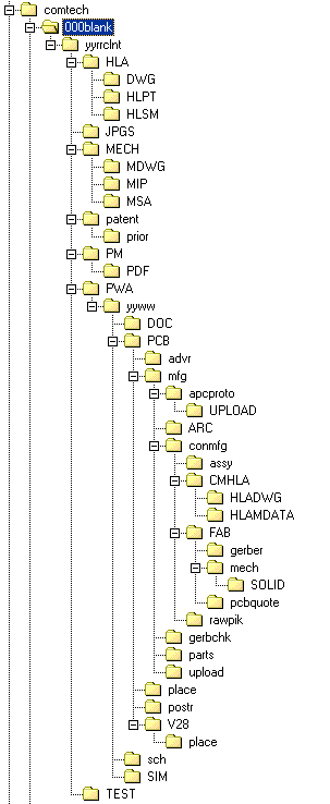
The COMTECH.zip is a zip file. It contains a sample structure for the parts management database. In each database there are multiple tables and queries that are used to format the forms, subforms and reports. The zip file on this page will extract to the correct directory structure. I've assumed C: since everybody has one.
|
|-comtech\
| |-000blank\
| | |-db1.mdb (can be anywhere)
| |
| |-mastpart\
| |-mastpart.mdb (must reside in this path)
|
|-newdsgn
|-parts
|-pcb
|-sch
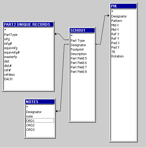
The other table called Notes is used to store miscellaneous information and part ordering flags for three separate in-house builds (I call them hand-builds).
Two tables will be created from Protel, one from the schematic, the other from the PCB. The schematic table is created using the BOM report in CSV format from Protel. I only export the Part Type, Description and Designator fields, along with Part Fields 5, 6, 7, and 8 which I use for general info that is circuit/design specific. Things such as whether the part is to be placed or not, or if a socket is required (you can also note this in the scheme by adding a special no part symbol that carries the socket, bolt, whatever). How you want to handle sockets and hardware is up to you. Just be consistent within the design. This is another reason I decided to use this system because I can adjust it for each client. I don't normally include non-electrical hardware since I'd rather have this in the higher level assembly BOM's that accompany mechanicals/solid models. But some CM's have different requirements, as do some clients.
The CSV is imported into Access using the Get External Data > Import option under the File menu. The name is set to be SCHOUT unless you want to adjust the queries each time. I use the same name since each design lives in it's own database; it makes copying the 000blank database to a new design easier.
The next file to import is the pik and place file from the PCB. I typically use the standard Protel format (space delimited) since I've got to bring it into Excel to get rid of the mil suffix. Import this into Access as PIK.
In the sample file (\newdsgn\db1.mdb) open the form main QUERY form USE THIS FOR MOST EDITING and edit the parts. Just hit enter at both prompts and all parts in the sample design are listed. This form uses the query called query ask and prompts for the part type and reference designator. If you leave both fields blank and hit enter at each prompt, the entire project will be available to the form. Navigation is by way of the standard Access controls. This form incorporates two subforms, one for the linked mastpart table (Part 2 Unique…) and the internal Notes table.
As you peruse the database using the main QUERY… form, note the lack of an entry for both of the HDR2X1-100 parts. If you look directly in the PART2 UNIQUE RECORDS table you'll see that indeed, no such part exists. While in the main QUERY… form, go to the entry for either of the HDR2X1-100 listings and enter a part description. Use the previous HDR3X1-100 as a template. You'll notice that second instance of the HDR2X1-100 was updated as well. In fact, any other design you create will now link as long as the Part Type description is correct.
The reports contained in the blank and sample databases are typical of the kind of control possible with parts management. Just add the company logo. This is just a sample to explain some of the concepts of relational databases and how they can be used to capture, modify and present data. For example, if you right click on the query called export for cm, and save it externally to an Excel spreadsheet, you can quickly create a file that any CM can import to their MRP and CAM systems. If you use a certain CM every time, you can modify and create the perfect system of tables, queries, forms and reports to satisfy both the CM and your boss/client.
Qualecad
Here's a wayback capture of the old qualecad site:https://web.archive.org/web/20141218002914/http://qualecad.com/
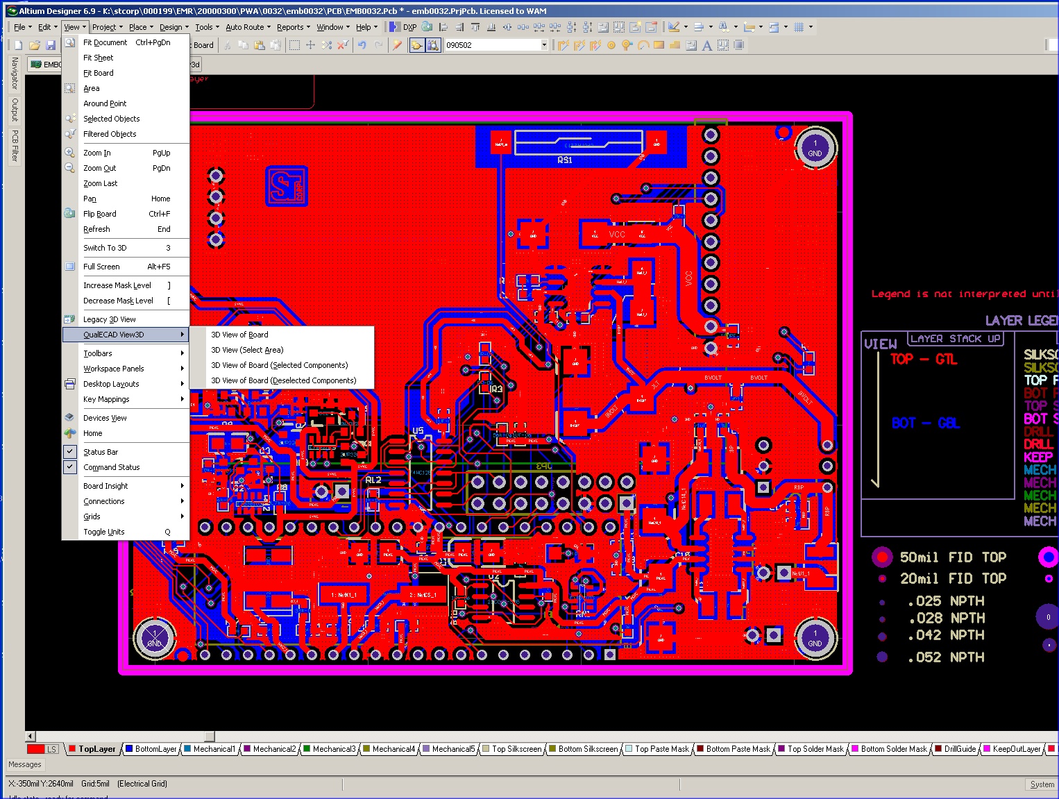
Years ago, back before Protel/Altium natively supported true 3D information, a program called Qualecad offered a plug in that added an entry to the View menu.
I really don't do a lot of 3D in my board layout; for one I do mostly top down designs that originate in Solidworks - shiny shoes sales and project management geeks get all excited about 3D models, not so much with board layouts (ya know the stuff that actually makes it work). Secondly, programs like Solidworks, Pro-E/Creo, etc... can barely handle 3D and third, Altium is already resource-starved - a lot of designs I do are quite large.
And with as many PCB's I do in a year, I really need speed and reliability in my CAD tools.
Back to Qualecad, I had noticed that he had this interesting report generator that would print individual sheets of the 3D board with all the components of a specific part type. For instance it would create a document of the 3D board and where all the 10K resistors were, and continue to produce pages of these 3D views with each part type that was on the board.
I contacted him and mentioned "... that 3D thing is great but could you tweak your program to just give me a 2D board outline with holes, pads, and silkscreen, where it would highlight the silkscreen for the uniques part types on each page?"
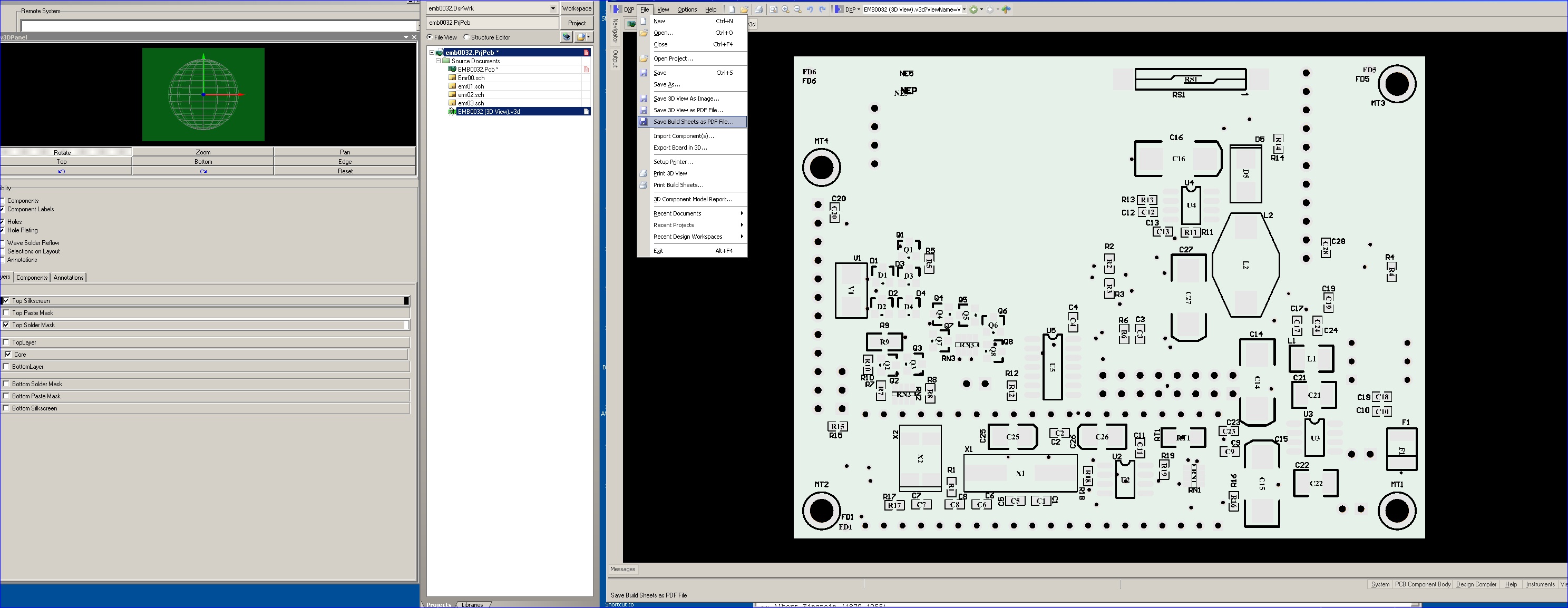
He did it. Viola - build sheets to hand to a tech for actually hand building the thing.
To the right are screen shots of how it integrated and looked in Altium 6.9.
A link to a build sheet generated from it:
http://www.ajawamnet.com/ajawamnet/parts/EMB0032TopSideBuildSheets.pdf
Fig
2. Typical design Sub-directory structure.
Click images for full size screen shots